4.2 KiB
HannaBox
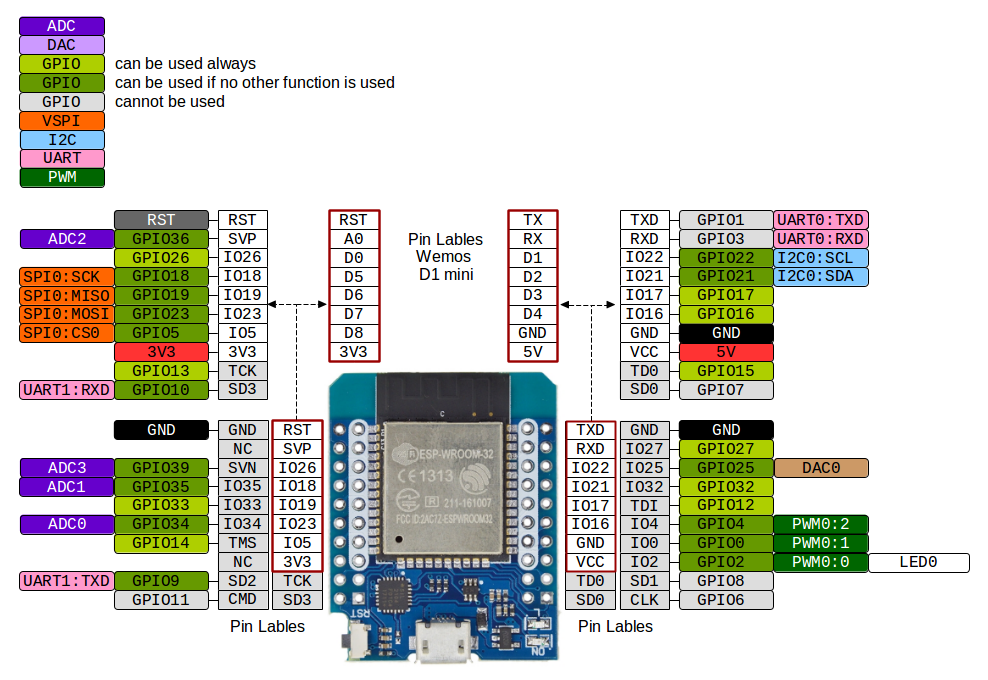
Microcontroller
D1 Mini ESP32 Due to mp3 playback it needs a multicore esp 32:
This library only works on multi-core ESP32 chips like the ESP32-S3. It does not work on the ESP32-S2 or the ESP32-C3 warning
Pins
Amplifier
26 -> DIN
27 -> BCLK
25 -> LRC
5V -> Vin
GND -> GND
SD Card
CS -> 22 (D1)
MOSI -> 23 (D7)
CLK -> 18 (D5)
MISO -> 19 (D6)
RFID Reader
SOA -> 32
SCK -> 18
MOSI -> 23
MISO -> 19
IRQ -> NC
GND -> GND
RST -> 33
3.3V -> 3.3V
Registers
Writing 0x7F to the "ComIEnReg" means the following:

    Bit 7: IRqInv=0 - Interrupts are active high
    Bit 6: TxIEn=1 - Transmitter interrupt is enabled
    Bit 5: RxIEn=1 - Receive interrupt is enabled
    Bit 4: IdleIEn=1 - Idle interrupt is enabled
    Bit 3: HiAlertIEn=1 - "High Alert" interrupt is enabled
    Bit 2: LoAlertIEn=1 - "Low Alert" interrupt is enabled
    Bit 1: ErrIEn=1 - Error interrupt is enabled
    Bit 0: TimerIEn=1 - Timer interrupt is enabled

The bits in the register "ComIrqReg" have the following meaning:

    Bit 7: Set1 - when written as 1, a bit value of 1 in bits 6-0 of the byte written set the corresponding register bit; when written as 0, bits 6-0 clear the corresponding register bit
    Bit 6: TxIRq - Set when the last bit of Tx data has been sent
    Bit 5: RxIRq - Set when the receiver detects the end of a valid data stream
    Bit 4: IdleIRq - Set when the CommandReg changes the command field to the idle command
    Bit 3: HiAlertIRq - Set when the Status1 register HiAlert bit is set
    Bit 2: LoAlertIRq - Set when the Status1 register LoAlert bit is set
    Bit 1: ErrIRq - Set when any bit in ErrorReg gets set
    Bit 0: TimerIRq - Set when the TCounterValReg decrements to zero

Writing 0x14 to the "DivIEnReg" has the following meaning:

    Bit 7: IRQPushPull=0 - IRQ is an open-drain output pin
    Bit 6: reserved=0 - no known effect
    Bit 5: reserved=0 - effect unknown
    Bit 4: MfinActEn=1 - Allow the MFIN active interrupt request to trigger IRQ
    Bit 3: reserved=0 - boundedly undefined
    Bit 2: CRCIEn=1 - Permit the "DivIrqReg" bit CRCIRq to trigger IRQ
    Bit 1: reserved=0 - do not set to 1 on pain of nothing
    Bit 0: reserved=0 - has no purpose other than to confuse

The register "DivIrqReg" corresponds to "DivIrqEn", and has the following bit definitions:

    Bit 7: Set2 - when written as 1, a bit value of 1 in bits 6-0 of the byte written set the corresponding register bit; when written as 0, bits 6-0 clear the corresponding register bit
    Bit 6: reserved - don't ask
    Bit 5: reserved - don't tell
    Bit 4: MfinActIRq - MFIN is active
    Bit 3: reserved - just leave it at zero and back away slowly
    Bit 2: CRCIRq - when 1, the CalcCRC command is active and all data is processed
    Bit 1: reserved - nothing to see here
    Bit 0: reserved - are you feeling lucky, punk?
Interrupt method was not working because it seems reading a card does not trigger one.
See https://arduino.stackexchange.com/a/76285 and https://github.com/miguelbalboa/rfid/blob/master/examples/MinimalInterrupt/MinimalInterrupt.ino
Buttons
Start / Stop -> 17 and GND
Wake up / Next -> 04 and GND
Previous -> 16 and GND
System sounds
Place these sounds in the folder system on the SD card:
- sleep.mp3
- start.mp3
sleep.mp3 will be played just before the timed shutdown, start.mp3 will be played if the box started and initialized successfully.
Battery Voltage
The battery voltage is measured by the ADC of pin 13. A voltage divider halves the voltage so that the pin can not be overloaded (max 3.3V). The voltage divider consists of two 100kOHM resistors, the voltage is measured between them. One side is connected to the battery and the other to ground. Pin 13s ADC (ADC2) can not be used while WIFI is on... damn.
TODOs
- Card Reader with SPI. Configure hspi, second SPI channel? Or does SD Card + RFID run at the same channel?
Schematic without modules
Charging circuit
https://ww1.microchip.com/downloads/en/AppNotes/01149c.pdf MCP73837 ?